

How To Set Up System Registers And Memory Enviorment
Main Memory
References:
- Abraham Silberschatz, Greg Gagne, and Peter Baer Galvin, "Operating Organisation Concepts, Ninth Edition ", Chapter viii
viii.1 Background
- Obviously memory accesses and memory management are a very important part of modern reckoner operation. Every instruction has to be fetched from retentivity before it can be executed, and nearly instructions involve retrieving information from memory or storing data in memory or both.
- The advent of multi-tasking OSes compounds the complexity of memory management, because because as processes are swapped in and out of the CPU, so must their code and data be swapped in and out of memory, all at high speeds and without interfering with any other processes.
- Shared memory, virtual memory, the classification of memory as read-just versus read-write, and concepts similar copy-on-write forking all farther complicate the consequence.
viii.1.i Basic Hardware
- It should be noted that from the memory chips point of view, all memory accesses are equivalent. The retention hardware doesn't know what a particular part of memory is being used for, nor does information technology care. This is well-nigh true of the OS as well, although not entirely.
- The CPU can just admission its registers and primary memory. It cannot, for example, make direct access to the difficult drive, and so any information stored there must first be transferred into the main memory fries before the CPU can work with it. ( Device drivers communicate with their hardware via interrupts and "memory" accesses, sending short instructions for instance to transfer information from the hard drive to a specified location in main retentiveness. The disk controller monitors the double-decker for such instructions, transfers the data, and then notifies the CPU that the data is there with another interrupt, simply the CPU never gets directly access to the disk. )
- Retention accesses to registers are very fast, more often than not one clock tick, and a CPU may be able to execute more than ane auto instruction per clock tick.
- Retentiveness accesses to primary memory are comparatively slow, and may take a number of clock ticks to consummate. This would crave intolerable waiting by the CPU if it were not for an intermediary fast retentivity cache built into virtually mod CPUs. The basic idea of the cache is to transfer chunks of retentiveness at a time from the main memory to the cache, and then to access individual memory locations i at a fourth dimension from the cache.
- User processes must be restricted so that they only admission memory locations that "belong" to that detail procedure. This is usually implemented using a base annals and a limit register for each process, as shown in Figures 8.1 and eight.ii beneath. Every memory access fabricated past a user procedure is checked against these ii registers, and if a memory access is attempted outside the valid range, then a fatal error is generated. The Bone obviously has admission to all existing retention locations, as this is necessary to bandy users' code and data in and out of memory. It should also exist obvious that changing the contents of the base and limit registers is a privileged activity, allowed merely to the Bone kernel.
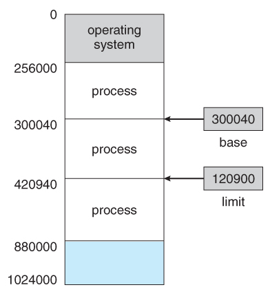
Figure viii.1 - A base and a limit register define a logical addresss infinite
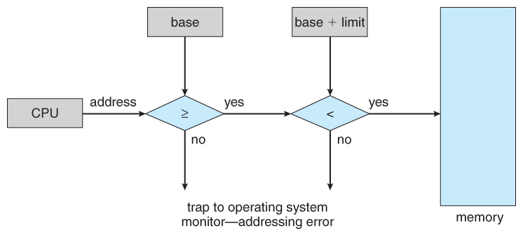
Effigy 8.ii - Hardware address protection with base of operations and limit registers8.1.2 Address Binding
- User programs typically refer to memory addresses with symbolic names such as "i", "count", and "averageTemperature". These symbolic names must be mapped or bound to concrete retentivity addresses, which typically occurs in several stages:
- Compile Time - If information technology is known at compile time where a program will reside in concrete memory, then absolute lawmaking can be generated by the compiler, containing actual physical addresses. Nevertheless if the load address changes at some later fourth dimension, so the plan will have to exist recompiled. DOS .COM programs utilize compile time binding.
- Load Time - If the location at which a program will be loaded is not known at compile time, then the compiler must generate relocatable code , which references addresses relative to the start of the programme. If that starting address changes, then the program must be reloaded but non recompiled.
- Execution Time - If a program can be moved around in memory during the grade of its execution, then binding must be delayed until execution time. This requires special hardware, and is the method implemented by nigh modern OSes.
- Effigy 8.iii shows the diverse stages of the binding processes and the units involved in each stage:
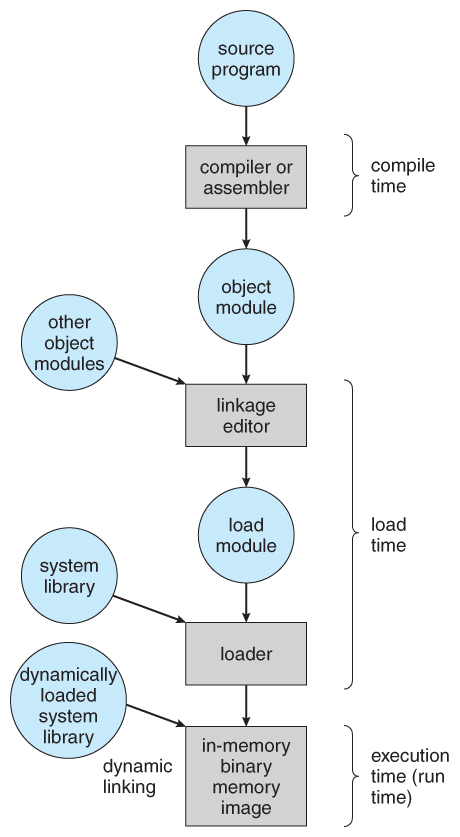
Figure 8.3 - Multistep processing of a user programme8.1.three Logical Versus Physical Address Space
- The accost generated by the CPU is a logical address , whereas the accost actually seen by the memory hardware is a physical address .
- Addresses spring at compile time or load time take identical logical and concrete addresses.
- Addresses created at execution time, however, have different logical and physical addresses.
- In this case the logical address is also known as a virtual address , and the two terms are used interchangeably by our text.
- The set up of all logical addresses used past a program composes the logical address infinite , and the set of all corresponding physical addresses composes the physical address infinite.
- The run fourth dimension mapping of logical to physical addresses is handled by the memory-management unit, MMU .
- The MMU can take on many forms. Ane of the simplest is a modification of the base-annals scheme described earlier.
- The base annals is now termed a relocation register , whose value is added to every memory request at the hardware level.
- Note that user programs never see concrete addresses. User programs work entirely in logical accost space, and any memory references or manipulations are done using purely logical addresses. Only when the address gets sent to the physical retentiveness chips is the physical memory address generated.
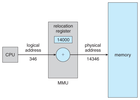
Effigy 8.iv - Dynamic relocation using a relocation register8.1.four Dynamic Loading
- Rather than loading an entire programme into memory at once, dynamic loading loads upwardly each routine every bit it is called. The reward is that unused routines need never be loaded, reducing total memory usage and generating faster plan startup times. The downside is the added complexity and overhead of checking to run into if a routine is loaded every time information technology is called and then then loading information technology up if information technology is non already loaded.
8.ane.5 Dynamic Linking and Shared Libraries
- With static linking library modules get fully included in executable modules, wasting both disk space and main memory usage, because every plan that included a certain routine from the library would have to have their own re-create of that routine linked into their executable lawmaking.
- With dynamic linking , however, only a stub is linked into the executable module, containing references to the actual library module linked in at run fourth dimension.
- This method saves disk space, considering the library routines do not demand to be fully included in the executable modules, just the stubs.
- We will as well larn that if the code section of the library routines is reentrant , ( meaning information technology does non modify the code while it runs, making it safe to re-enter it ), then master memory can be saved by loading only ane re-create of dynamically linked routines into memory and sharing the code amongst all processes that are meantime using it. ( Each process would have their own copy of the information department of the routines, but that may be small relative to the code segments. ) Plain the OS must manage shared routines in memory.
- An added benefit of dynamically linked libraries ( DLLs , also known equally shared libraries or shared objects on UNIX systems ) involves easy upgrades and updates. When a program uses a routine from a standard library and the routine changes, and so the programme must be re-built ( re-linked ) in gild to comprise the changes. However if DLLs are used, so as long as the stub doesn't alter, the program can exist updated merely by loading new versions of the DLLs onto the system. Version information is maintained in both the plan and the DLLs, so that a program can specify a detail version of the DLL if necessary.
- In do, the get-go time a program calls a DLL routine, the stub will recognize the fact and will supercede itself with the bodily routine from the DLL library. Farther calls to the same routine will access the routine directly and not incur the overhead of the stub admission. ( Post-obit the UML Proxy Pattern . )
- ( Additional information regarding dynamic linking is available at http://www.iecc.com/linker/linker10.html )
8.ii Swapping
- A process must be loaded into memory in order to execute.
- If there is not enough memory available to keep all running processes in retentivity at the same time, then some processes who are not currently using the CPU may have their retentiveness swapped out to a fast local disk chosen the backing shop.
viii.two.1 Standard Swapping
- If compile-fourth dimension or load-fourth dimension address binding is used, so processes must be swapped back into the same retention location from which they were swapped out. If execution time binding is used, then the processes tin be swapped back into any bachelor location.
- Swapping is a very slow process compared to other operations. For case, if a user process occupied x MB and the transfer charge per unit for the bankroll store were forty MB per 2d, then it would take i/4 second ( 250 milliseconds ) simply to do the information transfer. Calculation in a latency lag of 8 milliseconds and ignoring head seek time for the moment, and further recognizing that swapping involves moving old data out as well equally new data in, the overall transfer fourth dimension required for this swap is 512 milliseconds, or over half a second. For efficient processor scheduling the CPU time piece should be significantly longer than this lost transfer time.
- To reduce swapping transfer overhead, it is desired to transfer as little information as possible, which requires that the system know how much memory a process is using, as opposed to how much information technology might employ. Programmers can aid with this by freeing up dynamic retentiveness that they are no longer using.
- It is important to swap processes out of retentivity only when they are idle, or more to the point, but when there are no awaiting I/O operations. ( Otherwise the pending I/O operation could write into the incorrect procedure'southward memory infinite. ) The solution is to either swap but totally idle processes, or do I/O operations just into and out of Bone buffers, which are then transferred to or from process's main retention equally a second step.
- Most modernistic OSes no longer use swapping, because information technology is also tedious and there are faster alternatives available. ( e.g. Paging. ) Nonetheless some UNIX systems will all the same invoke swapping if the system gets extremely total, and then discontinue swapping when the load reduces once again. Windows 3.1 would employ a modified version of swapping that was somewhat controlled by the user, swapping process'southward out if necessary and then only swapping them back in when the user focused on that particular window.
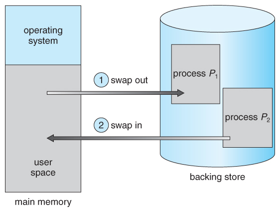
Figure 8.5 - Swapping of two processes using a disk as a bankroll shop
eight.2.2 Swapping on Mobile Systems ( New Section in 9th Edition )
- Swapping is typically not supported on mobile platforms, for several reasons:
- Mobile devices typically apply flash retention in identify of more spacious difficult drives for persistent storage, then there is not every bit much infinite bachelor.
- Flash memory can just be written to a limited number of times earlier it becomes unreliable.
- The bandwidth to flash memory is as well lower.
- Apple's IOS asks applications to voluntarily gratis upwards memory
- Read-simply data, e.g. code, is simply removed, and reloaded subsequently if needed.
- Modified data, e.g. the stack, is never removed, but . . .
- Apps that neglect to free up sufficient memory tin be removed by the OS
- Android follows a like strategy.
- Prior to terminating a process, Android writes its application land to flash retentiveness for quick restarting.
viii.3 Contiguous Retention Allocation
- Ane approach to retentiveness management is to load each procedure into a contiguous space. The operating system is allocated space commencement, commonly at either depression or high memory locations, and so the remaining available retentivity is allocated to processes as needed. ( The OS is unremarkably loaded low, because that is where the interrupt vectors are located, merely on older systems part of the OS was loaded high to make more room in low memory ( inside the 640K bulwark ) for user processes. )
8.3.1 Memory Protection ( was Memory Mapping and Protection )
- The system shown in Figure 8.six below allows protection against user programs accessing areas that they should non, allows programs to be relocated to different memory starting addresses equally needed, and allows the retentiveness space devoted to the OS to abound or shrink dynamically as needs modify.
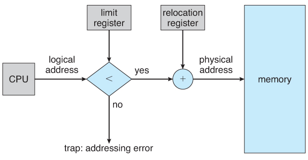
Figure 8.6 - Hardware support for relocation and limit registersviii.three.2 Retention Allocation
- One method of allocating contiguous memory is to divide all available memory into equal sized partitions, and to assign each procedure to their own division. This restricts both the number of simultaneous processes and the maximum size of each process, and is no longer used.
- An alternate approach is to keep a listing of unused ( gratuitous ) retentiveness blocks ( holes ), and to observe a hole of a suitable size whenever a process needs to exist loaded into memory. There are many unlike strategies for finding the "all-time" resource allotment of retention to processes, including the three virtually commonly discussed:
- First fit - Search the listing of holes until one is found that is large enough to satisfy the request, and assign a portion of that pigsty to that procedure. Whatever fraction of the hole not needed by the request is left on the free list equally a smaller pigsty. Subsequent requests may start looking either from the first of the list or from the point at which this search concluded.
- Best fit - Allocate the smallest hole that is big enough to satisfy the request. This saves large holes for other process requests that may need them later, just the resulting unused portions of holes may be likewise small to be of whatever use, and will therefore exist wasted. Keeping the free list sorted can speed up the process of finding the correct hole.
- Worst fit - Classify the largest pigsty available, thereby increasing the likelihood that the remaining portion will be usable for satisfying future requests.
- Simulations show that either first or best fit are better than worst fit in terms of both time and storage utilization. First and best fits are almost equal in terms of storage utilization, only first fit is faster.
8.3.3. Fragmentation
- All the retentivity allocation strategies suffer from external fragmentation , though kickoff and best fits experience the issues more than so than worst fit. External fragmentation means that the available memory is cleaved up into lots of little pieces, none of which is large enough to satisfy the side by side retentivity requirement, although the sum full could.
- The amount of retentivity lost to fragmentation may vary with algorithm, usage patterns, and some blueprint decisions such as which end of a hole to classify and which terminate to relieve on the free list.
- Statistical assay of first fit, for example, shows that for N blocks of allocated retention, another 0.v N will exist lost to fragmentation.
- Internal fragmentation also occurs, with all retentiveness resource allotment strategies. This is caused past the fact that memory is allocated in blocks of a fixed size, whereas the actual memory needed volition rarely exist that exact size. For a random distribution of retentiveness requests, on the average i/two block will be wasted per retentiveness request, because on the average the concluding allocated block will be merely half full.
- Note that the same issue happens with hard drives, and that modern hardware gives us increasingly larger drives and memory at the expense of ever larger cake sizes, which translates to more memory lost to internal fragmentation.
- Some systems apply variable size blocks to minimize losses due to internal fragmentation.
- If the programs in retention are relocatable, ( using execution-time accost binding ), and then the external fragmentation problem tin can be reduced via compaction , i.e. moving all processes downwards to 1 terminate of physical retentivity. This but involves updating the relocation register for each process, as all internal work is done using logical addresses.
- Another solution every bit we volition meet in upcoming sections is to permit processes to employ not-contiguous blocks of physical memory, with a split relocation register for each block.
eight.4 Partition
eight.4.1 Basic Method
- Most users ( programmers ) do non think of their programs as existing in one continuous linear address infinite.
- Rather they tend to remember of their retentiveness in multiple segments , each dedicated to a item use, such as lawmaking, information, the stack, the heap, etc.
- Memory sectionalization supports this view by providing addresses with a segment number ( mapped to a segment base of operations address ) and an offset from the offset of that segment.
- For example, a C compiler might generate 5 segments for the user code, library code, global ( static ) variables, the stack, and the heap, as shown in Figure viii.7:
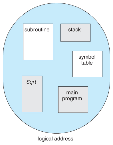
Figure 8.7 Programmer's view of a plan.
8.4.two Segmentation Hardware
- A segment tabular array maps segment-offset addresses to physical addresses, and simultaneously checks for invalid addresses, using a system like to the page tables and relocation base registers discussed previously. ( Note that at this point in the give-and-take of segmentation, each segment is kept in contiguous memory and may be of different sizes, but that segmentation tin also exist combined with paging every bit we shall run across shortly. )
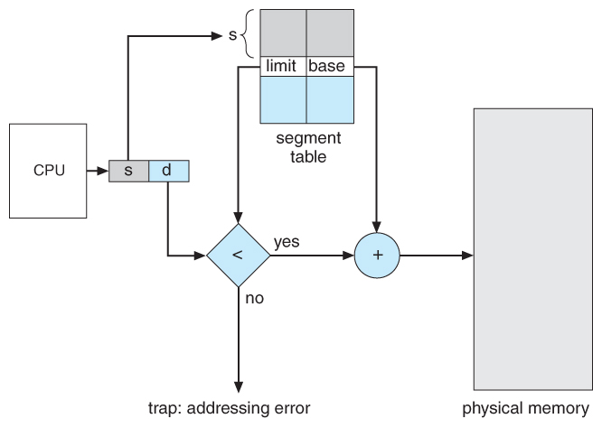
Figure viii.8 - Segmentation hardware
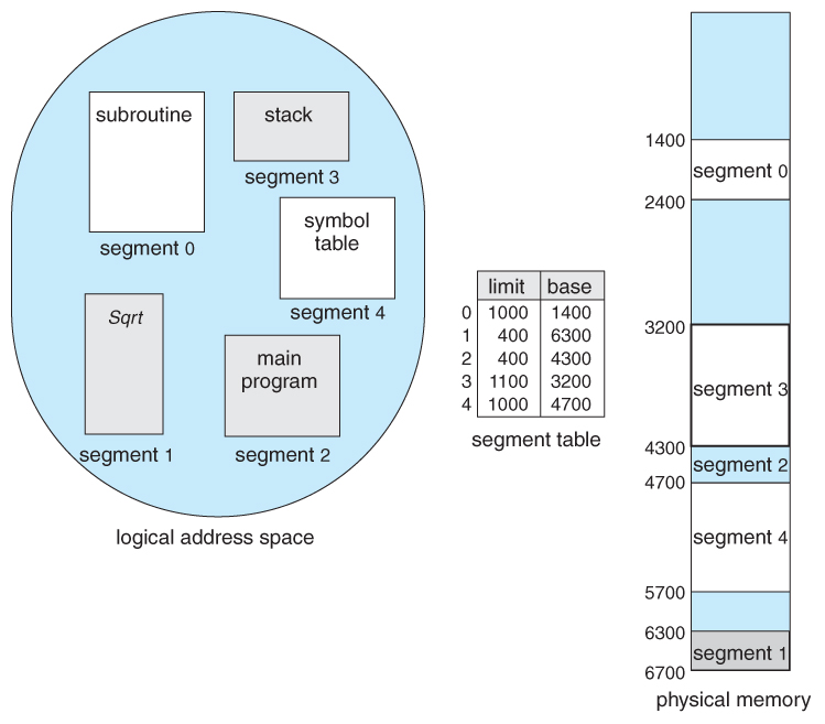
Figure 8.ix - Example of division
8.5 Paging
- Paging is a memory management scheme that allows processes physical memory to be discontinuous, and which eliminates problems with fragmentation past allocating retentiveness in equal sized blocks known as pages .
- Paging eliminates virtually of the problems of the other methods discussed previously, and is the predominant memory management technique used today.
viii.5.i Bones Method
- The basic thought behind paging is to carve up physical memory into a number of equal sized blocks called frames , and to divide a programs logical memory space into blocks of the same size called pages.
- Whatever folio ( from any process ) can be placed into any bachelor frame.
- The page tabular array is used to await up what frame a detail page is stored in at the moment. In the following example, for instance, page 2 of the plan'due south logical memory is currently stored in frame 3 of physical memory:

Figure eight.10 - Paging hardware
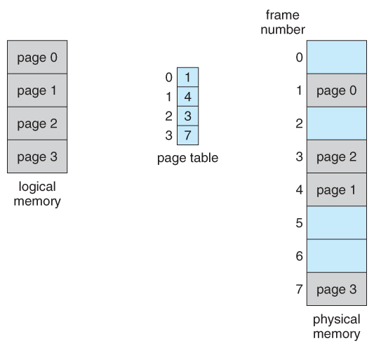
Figure 8.11 - Paging model of logical and concrete memory
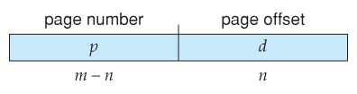
- A logical address consists of two parts: A page number in which the address resides, and an offset from the beginning of that page. ( The number of $.25 in the page number limits how many pages a unmarried process can accost. The number of bits in the starting time determines the maximum size of each page, and should correspond to the system frame size. )
- The page tabular array maps the folio number to a frame number, to yield a physical address which likewise has ii parts: The frame number and the get-go within that frame. The number of bits in the frame number determines how many frames the arrangement can address, and the number of bits in the offset determines the size of each frame.
- Page numbers, frame numbers, and frame sizes are determined by the compages, but are typically powers of 2, allowing addresses to be split at a certain number of bits. For example, if the logical address size is two^m and the folio size is ii^n, then the high-order one thousand-n bits of a logical address designate the page number and the remaining n bits correspond the offset.
- Note also that the number of bits in the page number and the number of bits in the frame number do not take to exist identical. The former determines the accost range of the logical address infinite, and the latter relates to the physical address space.
- ( DOS used to use an addressing scheme with 16 fleck frame numbers and 16-bit offsets, on hardware that but supported 24-fleck hardware addresses. The result was a resolution of starting frame addresses finer than the size of a single frame, and multiple frame-offset combinations that mapped to the aforementioned physical hardware accost. )
- Consider the following micro example, in which a process has sixteen bytes of logical memory, mapped in 4 byte pages into 32 bytes of physical retention. ( Presumably some other processes would be consuming the remaining 16 bytes of physical retention. )
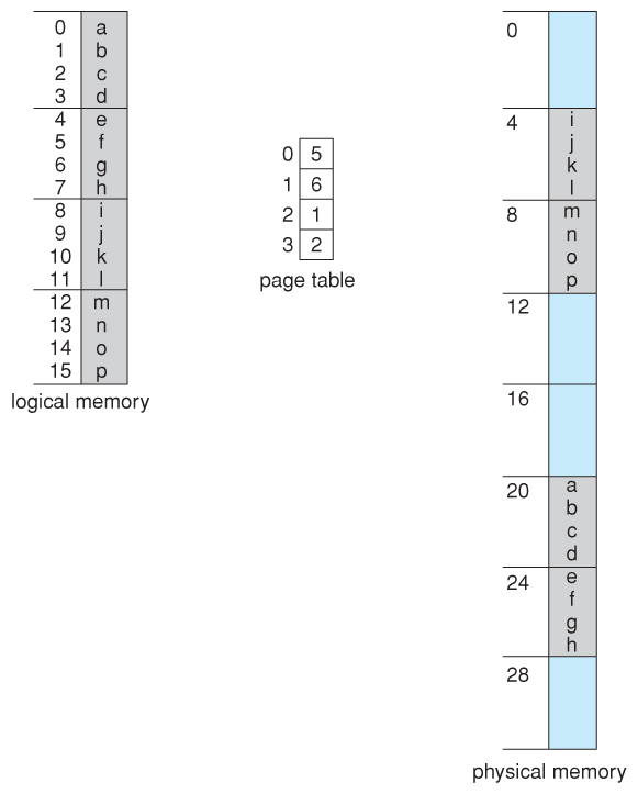
Figure 8.12 - Paging example for a 32-byte memory with 4-byte pages
- Note that paging is like having a table of relocation registers, one for each page of the logical memory.
- There is no external fragmentation with paging. All blocks of physical memory are used, and at that place are no gaps in between and no problems with finding the right sized hole for a particular chunk of memory.
- In that location is, however, internal fragmentation. Memory is allocated in chunks the size of a page, and on the average, the last folio volition only be half full, wasting on the average half a page of retention per process. ( Peradventure more than, if processes go along their code and data in separate pages. )
- Larger page sizes waste product more retentiveness, but are more efficient in terms of overhead. Modern trends have been to increase page sizes, and some systems even have multiple size pages to try and make the best of both worlds.
- Folio tabular array entries ( frame numbers ) are typically 32 flake numbers, assuasive admission to 2^32 physical folio frames. If those frames are four KB in size each, that translates to 16 TB of addressable physical memory. ( 32 + 12 = 44 bits of physical accost space. )
- When a procedure requests memory ( eastward.g. when its code is loaded in from disk ), free frames are allocated from a free-frame listing, and inserted into that process'due south page table.
- Processes are blocked from accessing anyone else's memory because all of their retentivity requests are mapped through their page table. There is no way for them to generate an address that maps into any other process'due south memory space.
- The operating organization must keep track of each individual procedure'south folio table, updating information technology whenever the process's pages get moved in and out of retention, and applying the correct page table when processing arrangement calls for a detail process. This all increases the overhead involved when swapping processes in and out of the CPU. ( The currently agile page table must be updated to reflect the process that is currently running. )
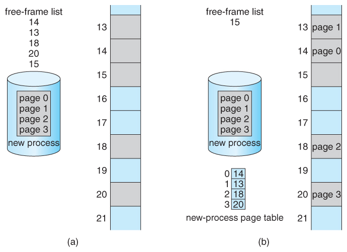
Figure eight.13 - Free frames (a) before resource allotment and (b) later on resource allotmentviii.5.ii Hardware Support
- Page lookups must be washed for every memory reference, and whenever a procedure gets swapped in or out of the CPU, its page table must be swapped in and out too, along with the education registers, etc. It is therefore advisable to provide hardware back up for this operation, in order to make information technology equally fast as possible and to brand process switches every bit fast as possible also.
- One pick is to use a set of registers for the page tabular array. For example, the DEC PDP-11 uses 16-flake addressing and 8 KB pages, resulting in only 8 pages per process. ( It takes xiii bits to address 8 KB of get-go, leaving only 3 $.25 to define a folio number. )
- An alternate choice is to store the page table in main retentivity, and to use a single register ( called the page-table base register, PTBR ) to record where in retentiveness the page table is located.
- Process switching is fast, because merely the single register needs to be changed.
- However retentivity access just got half as fast, because every retention access now requires 2 memory accesses - I to fetch the frame number from memory and and so another ane to access the desired memory location.
- The solution to this problem is to utilise a very special high-speed memory device chosen the translation look-aside buffer, TLB.
- The benefit of the TLB is that it can search an entire table for a cardinal value in parallel, and if it is found anywhere in the table, then the corresponding lookup value is returned.
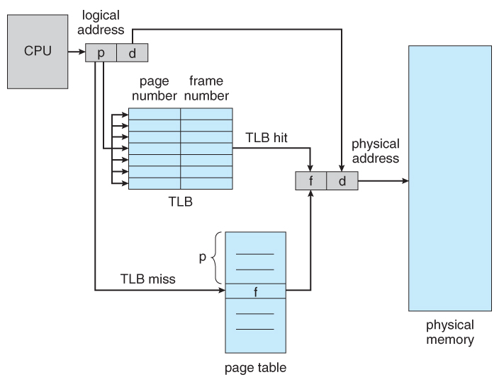
Figure eight.fourteen - Paging hardware with TLB
- The TLB is very expensive, however, and therefore very small. ( Not large plenty to concur the entire page table. ) It is therefore used equally a cache device.
- Addresses are showtime checked against the TLB, and if the info is not there ( a TLB miss ), then the frame is looked up from main memory and the TLB is updated.
- If the TLB is total, then replacement strategies range from to the lowest degree-recently used, LRU to random.
- Some TLBs let some entries to be wired downward , which means that they cannot be removed from the TLB. Typically these would be kernel frames.
- Some TLBs store address-space identifiers, ASIDs , to continue runway of which process "owns" a detail entry in the TLB. This allows entries from multiple processes to exist stored simultaneously in the TLB without granting 1 process access to another process'due south memory location. Without this feature the TLB has to be flushed clean with every procedure switch.
- The percentage of time that the desired information is found in the TLB is termed the hit ratio .
- ( 8th Edition Version: ) For instance, suppose that it takes 100 nanoseconds to access main memory, and but 20 nanoseconds to search the TLB. And then a TLB hitting takes 120 nanoseconds full ( 20 to discover the frame number so another 100 to go get the information ), and a TLB miss takes 220 ( 20 to search the TLB, 100 to go become the frame number, and then another 100 to go become the data. ) Then with an 80% TLB hit ratio, the boilerplate retentiveness access time would be:
0.eighty * 120 + 0.20 * 220 = 140 nanoseconds
for a 40% slowdown to get the frame number. A 98% hit rate would yield 122 nanoseconds boilerplate access fourth dimension ( you should verify this ), for a 22% slowdown.
- ( Ninth Edition Version: ) The ninth edition ignores the xx nanoseconds required to search the TLB, yielding
0.fourscore * 100 + 0.20 * 200 = 120 nanoseconds
for a twenty% slowdown to become the frame number. A 99% hit rate would yield 101 nanoseconds average access time ( you should verify this ), for a 1% slowdown.
8.v.3 Protection
- The page table tin also help to protect processes from accessing retention that they shouldn't, or their own memory in ways that they shouldn't.
- A bit or bits tin exist added to the page table to classify a folio equally read-write, read-just, read-write-execute, or some combination of these sorts of things. Then each memory reference tin can be checked to ensure it is accessing the memory in the appropriate mode.
- Valid / invalid $.25 can exist added to "mask off" entries in the page tabular array that are non in use by the current process, equally shown by example in Figure viii.12 below.
- Note that the valid / invalid bits described to a higher place cannot block all illegal retentiveness accesses, due to the internal fragmentation. ( Areas of memory in the last page that are non entirely filled by the process, and may contain data left over past whoever used that frame last. )
- Many processes practice not apply all of the page table available to them, specially in modern systems with very large potential page tables. Rather than waste memory by creating a full-size page table for every procedure, some systems employ a page-tabular array length annals, PTLR , to specify the length of the page table.
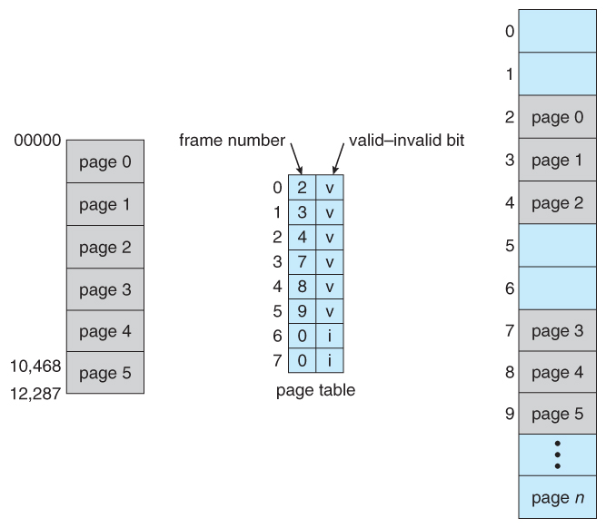
Figure viii.15 - Valid (v) or invalid (i) bit in page table8.5.4 Shared Pages
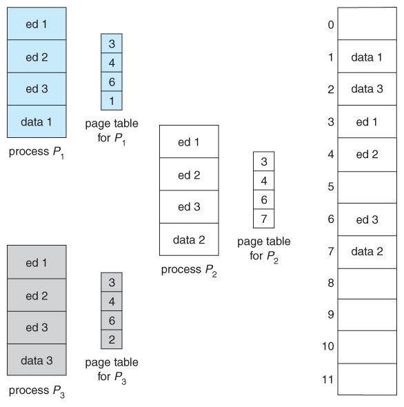
- Paging systems tin make it very like shooting fish in a barrel to share blocks of memory, by but duplicating page numbers in multiple folio frames. This may be done with either code or data.
- If lawmaking is reentrant , that ways that it does not write to or change the code in whatever manner ( it is not self-modifying ), and it is therefore rubber to re-enter information technology. More importantly, it means the code can be shared by multiple processes, so long every bit each has their own copy of the data and registers, including the instruction register.
- In the example given below, iii different users are running the editor simultaneously, merely the code is merely loaded into memory ( in the page frames ) one time.
- Some systems also implement shared memory in this fashion.
Effigy 8.16 - Sharing of lawmaking in a paging environs
8.vi Construction of the Page Table
viii.vi.ane Hierarchical Paging
- Most modernistic estimator systems support logical address spaces of 2^32 to 2^64.
- With a 2^32 address infinite and 4K ( two^12 ) page sizes, this leave 2^20 entries in the page table. At 4 bytes per entry, this amounts to a 4 MB page table, which is as well large to reasonably go on in contiguous memory. ( And to swap in and out of memory with each procedure switch. ) Annotation that with 4K pages, this would take 1024 pages simply to hold the page table!
- One option is to utilize a 2-tier paging system, i.east. to page the page table.
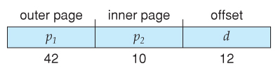
- For example, the 20 $.25 described in a higher place could be broken down into two 10-bit page numbers. The first identifies an entry in the outer page table, which identifies where in memory to detect one page of an inner page tabular array. The 2nd x $.25 finds a specific entry in that inner page table, which in turn identifies a detail frame in physical memory. ( The remaining 12 bits of the 32 flake logical accost are the offset within the 4K frame. )
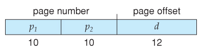
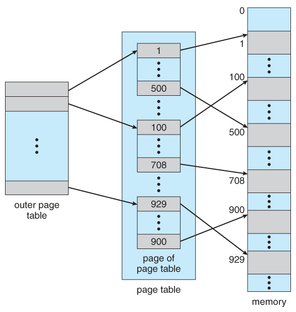
Figure 8.17 A ii-level folio-table scheme
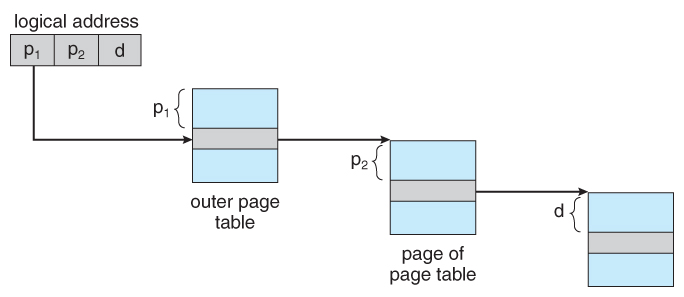
Figure eight.18 - Address translation for a ii-level 32-bit paging architecture
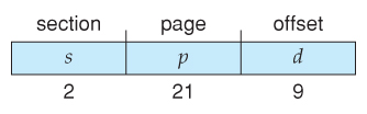
- VAX Architecture divides 32-bit addresses into 4 equal sized sections, and each page is 512 bytes, yielding an address form of:
- With a 64-chip logical accost space and 4K pages, there are 52 bits worth of page numbers, which is still too many even for 2-level paging. One could increment the paging level, but with 10-fleck folio tables it would take 7 levels of indirection, which would be prohibitively wearisome memory access. So some other approach must be used.
64-bits Two-tiered leaves 42 bits in outer table
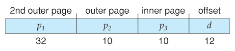
Going to a quaternary level still leaves 32 $.25 in the outer table.
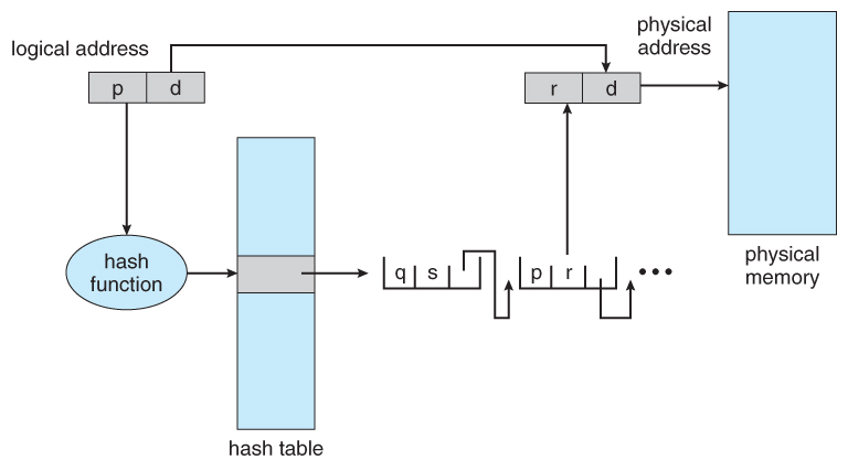
eight.half dozen.2 Hashed Page Tables
- One common information structure for accessing data that is sparsely distributed over a broad range of possible values is with hash tables . Effigy 8.16 below illustrates a hashed page tabular array using chain-and-bucket hashing:
Effigy 8.19 - Hashed page table8.six.3 Inverted Page Tables
- Another arroyo is to use an inverted page table . Instead of a table listing all of the pages for a particular process, an inverted page table lists all of the pages currently loaded in memory, for all processes. ( I.east. there is ane entry per frame instead of ane entry per page . )
- Access to an inverted folio table can exist ho-hum, as it may be necessary to search the entire table in order to discover the desired page ( or to find that it is not there. ) Hashing the table can assistance speedup the search procedure.
- Inverted folio tables prohibit the normal method of implementing shared memory, which is to map multiple logical pages to a mutual physical frame. ( Because each frame is now mapped to one and only one process. )
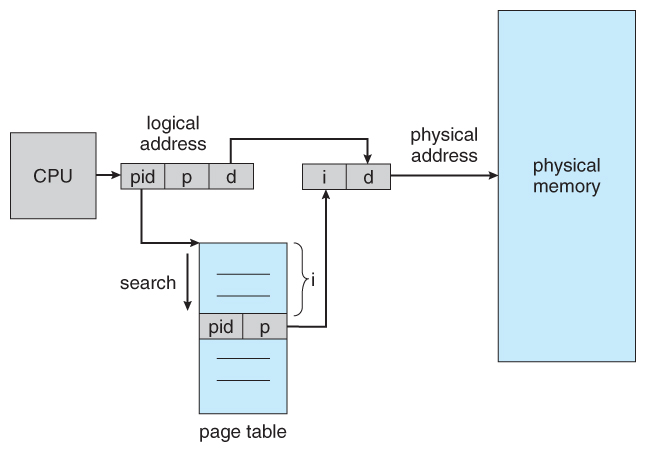
Figure 8.20 - Inverted folio table
8.six.4 Oracle SPARC Solaris ( Optional, New Section in 9th Edition )
8.7 Example: Intel 32 and 64-chip Architectures ( Optional )
8.seven.1.1 IA-32 Partitioning
- The Pentium CPU provides both pure segmentation and partitioning with paging. In the latter example, the CPU generates a logical accost ( segment-offset pair ), which the sectionalisation unit converts into a logical linear address, which in turn is mapped to a physical frame by the paging unit, as shown in Figure 8.21:
![]()
Figure 8.21 - Logical to physical address translation in IA-32
8.7.1.ane IA-32 Segmentation
- The Pentium architecture allows segments to be as big as iv GB, ( 24 bits of get-go ).
- Processes can have as many as 16K segments, divided into two 8K groups:
- 8K private to that item process, stored in the Local Descriptor Table, LDT.
- 8K shared amid all processes, stored in the Global Descriptor Table, GDT.
- Logical addresses are ( selector, offset ) pairs, where the selector is made up of 16 $.25:
- A 13 bit segment number ( up to 8K )
- A ane scrap flag for LDT vs. GDT.
- 2 bits for protection codes.
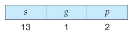
- The descriptor tables incorporate eight-byte descriptions of each segment, including base and limit registers.
- Logical linear addresses are generated by looking the selector upward in the descriptor table and adding the advisable base address to the offset, every bit shown in Figure eight.22:
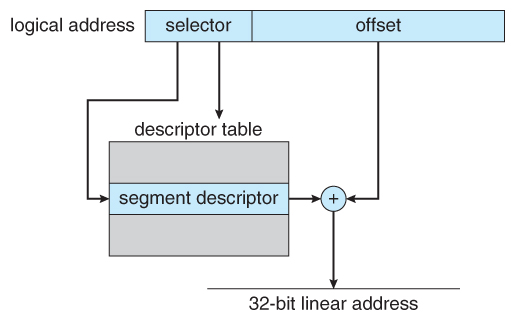
Figure 8.22 - IA-32 segmentation8.vii.1.ii IA-32 Paging
- Pentium paging normally uses a two-tier paging scheme, with the first 10 bits beingness a page number for an outer folio table ( a.thousand.a. folio directory ), and the side by side 10 bits being a folio number within i of the 1024 inner folio tables, leaving the remaining 12 $.25 equally an showtime into a 4K page.
- A special bit in the page directory can signal that this page is a 4MB page, in which instance the remaining 22 bits are all used as starting time and the inner tier of folio tables is not used.
- The CR3 register points to the page directory for the current procedure, equally shown in Figure viii.23 below.
- If the inner page tabular array is currently swapped out to deejay, then the folio directory volition accept an "invalid flake" fix, and the remaining 31 bits provide data on where to detect the swapped out folio table on the deejay.
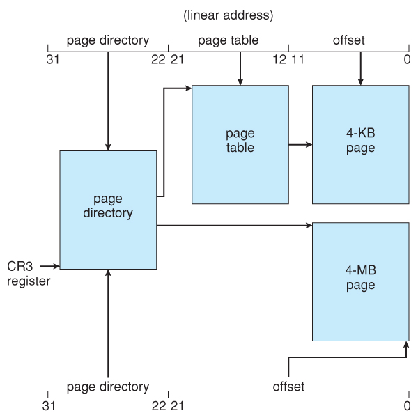
Figure eight.23 - Paging in the IA-32 compages.
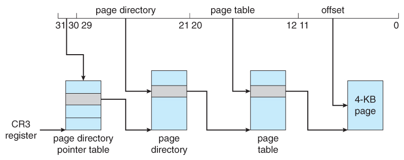
Effigy viii.24 - Folio address extensions.8.7.2 x86-64
Effigy 8.25 - x86-64 linear address.
8.viii Example: ARM Architecture ( Optional )
![]()
Figure 8.26 - Logical address translation in ARM.
Old 8.7.three Linux on Pentium Systems - Omitted from the 9th Edition
- Because Linux is designed for a wide variety of platforms, some of which offer only express support for sectionalisation, Linux supports minimal segmentation. Specifically Linux uses only 6 segments:
- Kernel code.
- Kerned data.
- User lawmaking.
- User information.
- A task-state segment, TSS
- A default LDT segment
- All processes share the aforementioned user code and data segments, because all process share the aforementioned logical address space and all segment descriptors are stored in the Global Descriptor Table. ( The LDT is generally not used. )
- Each procedure has its own TSS, whose descriptor is stored in the GDT. The TSS stores the hardware state of a process during context switches.
- The default LDT is shared by all processes and generally non used, but if a process needs to create its own LDT, information technology may practise then, and employ that instead of the default.
- The Pentium architecture provides two $.25 ( iv values ) for protection in a segment selector, but Linux only uses two values: user mode and kernel mode.
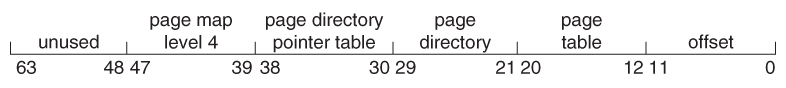
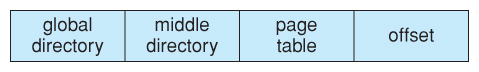
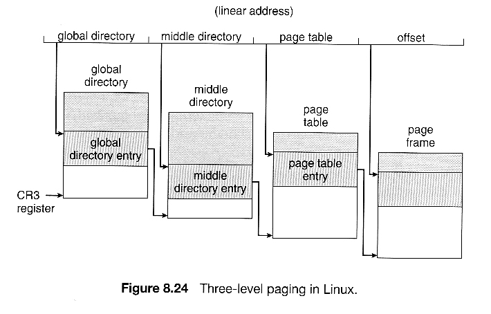
- Because Linux is designed to run on 64-flake besides as 32-chip architectures, it employs a three-level paging strategy as shown in Figure eight.24, where the number of $.25 in each portion of the address varies by compages. In the case of the Pentium architecture, the size of the middle directory portion is gear up to 0 bits, finer bypassing the middle directory.
8.8 Summary
-
( For a fun and like shooting fish in a barrel explanation of paging, you may want to read almost The Paging Game. )

How To Set Up System Registers And Memory Enviorment,
Source: https://www.cs.uic.edu/~jbell/CourseNotes/OperatingSystems/8_MainMemory.html
Posted by: welchlethemstes61.blogspot.com
0 Response to "How To Set Up System Registers And Memory Enviorment"
Post a Comment